news
how to adjust the speed of permanent magnet synchronous motor
2023-03-14 15:12:16来源:
permanent magnet synchronous motor, the most basic structure of the stator and rotor. the stator is similar to the rotor of asynchronous motor and is made of insulated copper wire. the rotor contains permanent magnets and has a certain number of poles to establish the main magnetic field of the motor.
compared with asynchronous motors, the relationship between electricity, magnetism and force of permanent magnet synchronous motors is simpler, and the decoupling of current and torque can be realized through certain coordinate transformation.
1. coordinate transformation
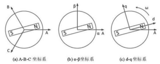
list the relevant coordinate transformation used in the variable frequency speed regulation of permanent magnet synchronous motor. the a-b-c coordinate system takes the center of the stator core as the origin, the three-phase winding of the stator as three directions a, b and c as the axis, and the included angle between the shaft and the shaft is 120 °. α-β the coordinate system is in the same plane as the a-b-c coordinate system and shares the same origin, α axis coincides with axis a, β axis and α the shaft is at a 90 ° angle. in the d-q coordinate system, the d axis coincides with the n pole of the permanent magnet of the rotor and rotates with the rotor. the q axis and d axis form a 90 ° angle in the counterclockwise direction.

2. speed regulation below fundamental frequency
field-oriented control: field-oriented control, that is, in the d-q coordinate system, the part of the motor parameters, such as the excitation current, that affects the torque is the component of the parameter projected onto the q-axis. the part projected onto the d axis does not need to be considered, that is, the commonly called id=0 method. in this method, the decisive factor of the maximum output speed of the motor is the maximum supply voltage of the controller. the limitation of the field-oriented control strategy is that it cannot reflect the changes of some parameters of the excitation current that affect the magnetic field, so it is not possible to carry out field-weakening control.
3. speed regulation above fundamental frequency
the starting point of the direct torque method is to directly influence the torque output value by controlling the parameters in the torque formula. select the moment angle as the control object. take the built-in rotor permanent magnet synchronous motor as an example to illustrate the specific method. under the condition of constant power supply voltage and stator magnetic field frequency, the real-time output torque of the motor is proportional to the sine value of the torque angle.
the electromagnetic torque value corresponding to each torque angle can be calculated offline to form a vector table and stored in the upper computer. during the operation of the motor controller, the torque and torque angle are observed in real time, and the original values in the table are extracted for comparison. if there is any discrepancy with the values in the table, adjust the power supply voltage value and correct the torque. direct torque method has good robustness, simple algorithm, and does not need coordinate transformation. it is a control method widely used in the early stage. however, the control accuracy of this method drops sharply at low speed. therefore, you can choose to use only below the fundamental frequency.
4. maximum torque current ratio control strategy
decouple the current in the d-q coordinate system, and then calculate the maximum torque current ratio of each component respectively, in order to obtain the maximum torque under the determined excitation current.
determine the existence of the maximum by taking the second derivative. in the speed regulation range, if the second derivative of the torque current ratio is less than 0, the maximum value of the torque current ratio exists.
